
About Multisim Software: Quick Functionality Overview Part II
In this article we continue talking about Multisim software and its basic functionality (the previous part you can read in Guide #35). The good news for beginners is that you can accomplish most actions through menus and dialog boxes without having to actually learn all peculiarities of Multisim. Menus and dialog boxes are useful because they give you visual reminders of most options with each step of creating the circuit. In the long run, you will want to learn the program deeper, because this article is more about the basics. In the following article we will show you how to change component values, analyze components, use a multimeter, and more.
Multisim Software Quick Functionality Overview. Part 2
Task: Multisim software quick functionality overview with examples (Part 2). Check out the first of Multisim examples.
Solution:
Change Component Values
To change component values, double-click on the component. This brings up a window that displays the properties of the component. Check Figure 7 for reference. Change R1 from 1k Ohm to 10 Ohms, R2 to 20 Ohms, R3 to 30 Ohms, and R4 to 40 Ohms. Also change the DV source from 0 V to 20 V. Figure 8 shows the completed circuit.
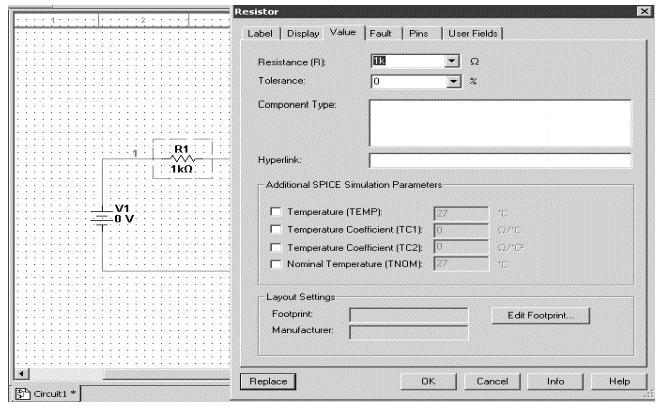 Figure 7: Change Component Values
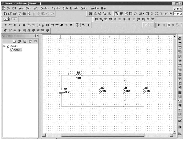 Figure 8: Completed Circuits
Grounding
All circuits must be grounded before the circuit can be simulated. Click on Ground in the toolbar to ground the circuit. If the circuit is not grounded Multisim will not run the simulation.
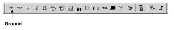 Figure 9: Grounding
Simulation
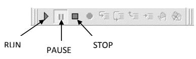 Figure 10: Simulation
Analyzing Components
Multisim offers multiple ways to analyze the circuit using virtual instruments.
Some of the basic instruments needed for this lab are described below.
Multimeter
Use the Multimeter to measure AC or DC voltage or current, and resistance or decibel loss between two nodes in a circuit. To use the Multimeter, click on the Multimeter button in the Instruments toolbar and click to place its icon on the workspace. Double-click on the icon to open the instrument face, which is used to enter settings and view measurements.
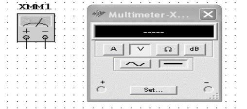 Figure 11: Multimeter
To measure Voltage, place the Multimeter in parallel with the component (Resistor, Voltage etc). To measure Current, place the Multimeter in series with the component. Refer to Figures 12 and 13.
 Figure 12: Measure Voltage
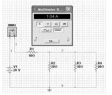 Figure 13: Measure Current
Wattmeter
The Wattmeter measures power. It is used to measure the magnitude of the active power, that is, the product of the voltage difference and the current flow through the terminals in a circuit.
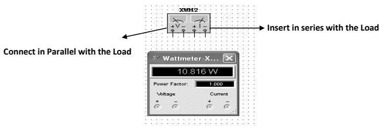 Figure 14: Wattmeter
To use the instrument, click on the Wattmeter button in the Instruments toolbar and click to place its icon on the workspace. The icon is used to wire the Wattmeter to the circuit. Double-click on the icon to open the instrument face, which is used to enter settings and view measurements. Refer to Figure 15 for more details.
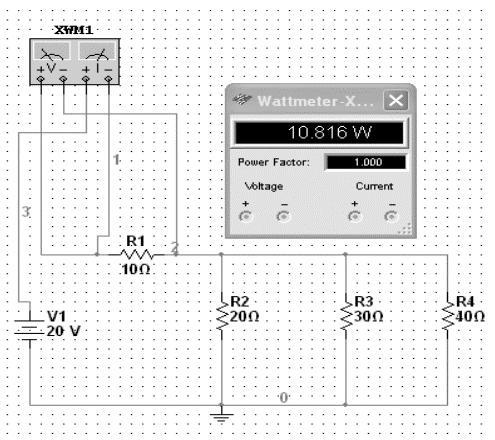 Figure 15: Wattmeter Connection
Agilent Multimeter
The Agilent Multimeter Instrument can also be used to measure and simulate circuits with more accuracy. To use the Multimeter, click on the Agilent Multimeter tool button, place its icon on the workspace, and double-click on the icon to open the instrument. Click on the Power button to switch on the instrument.
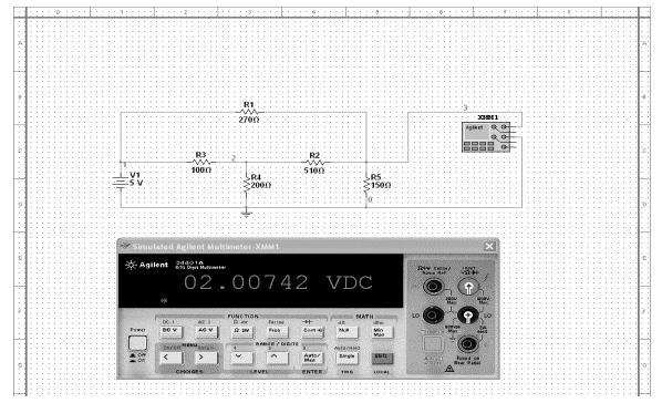 Figure 16: Agilent Multimeter
Ammeter
The Ammeter offers advantages over the multimeter for measuring current in a circuit. It takes up less space in a circuit and you can rotate its terminals to suit your layout. Always connect the ammeter in series with the load. To place Ammeter, click on View → Toolbar → Select Measurement Components. See Figure 17 on how to use Ammeter.
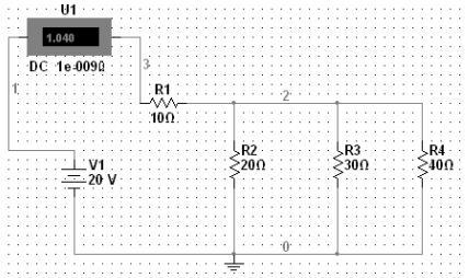 Figure 17: Ammeter
Voltmeter
Voltmeter offers advantages over the multimeter for measuring voltage in a circuit. Always connect the voltmeter in parallel with the load. The voltmeter can be found in the measurement toolbar.
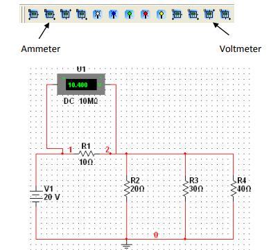 Figure 18: Voltmeter
Read Part 1: Multisim Examples: Quick Functionality Overview Part I